MAKING THE MOST OF SAFETY INTEGRITY LEVELS

By Khanjari Kumbhar

Insufficient training on safety processes puts industrial facilities at risk for accidents. Prioritizing safety and adopting vigorous safety solutions and standards can reduce such incidents drastically.

Read The White Paper

Risks mount wherever people store, process or handle hazardous or toxic materials. In the process industries, these risks are heightened because of their potential to affect numerous people. A spill of a toxic agent or an explosion could be hazardous to people within the plant or in the surrounding area.

There has been an increased focus on industrial safety worldwide. Major catastrophes at Seveso (Italy), Bhopal (India), Piper Alpha (U.K.) and Chernobyl (Ukraine) in the last few decades have brought the need for improved understanding and risk reduction approaches into sharp relief.

Compliance with standards to safeguard personnel and the environment is a priority for both legal and ethical reasons, as well as reducing life cycle costs. Effective safety solutions are needed to enable proactive protection, preventing injuries and saving lives. Eliminating risk entirely and bringing about a state of absolute safety is not practical. More realistically, risk can be categorized as being either negligible, tolerable or unacceptable. The foundation for any modern safety system is to reduce risk to an acceptable or tolerable level. In this context, safety can be defined as “freedom from unacceptable risk.”

The formula for risk is:
RISK = FREQUENCY OF OCCURENCE × SEVERITY OF CONSEQUENCE
INTRODUCTION TO SAFETY INSTRUMENTED SYSTEMS

In industrial plants there are many types of control systems that continuously manage process parameters such as temperature, flow, level and pressure. Such processes can create hazardous situations when they are out of control, and the basic process control system (BPCS) might not be able to maintain safe operation in the event of a failure. This is where the safety instrumented system (SIS) comes into play. The purpose of the SIS is to perform safety instrumented functions (SIFs) and, if necessary, shut down the process in an orderly manner. In other words, the SIS trips the process when it detects an out-of-limit or out-of-control condition. Common types of safety systems include emergency shutdown, fire and gas monitoring, critical process control, burner management, and turbo machinery control.

After a cost-benefit analysis is performed, it is recommended to invest in and maintain an SIS that is effective compared to the implications of a potential hazardous event. Plant safety systems require careful planning, designing, implementation and maintenance to see that the expected level of safety is realized and maintained, and that false alarms are minimized.

LEVEL SETTING

Safety Integrity Level (SIL) is defined as a relative level of risk reduction provided by a safety function, or it can specify a target level of risk reduction. SIL is a measurement of performance or probability of failure on demand (PFD) required for a SIF within an SIS based on the ANSI/ISA 84.01, IEC 61508 and IEC 61511 standards.

All organizational and technical risk reduction measures act as a counterweight to the risk potential. The values SIL 1 to SIL 4 are derived from the risk analysis. The greater the risk, the more reliable risk reduction measures must be implemented and, consequently, the greater reliability the components used must exhibit. Typically, as the SIL level increases, the cost and complexity of the system also increases.

The four SIL levels are determined based on several quantitative factors in combination with qualitative factors, such as development process and safety life cycle management. The requirements for a given SIL vary with the functional safety standards for given industries.

COMPELLING COMPLIANCE

The underlying need for the IEC/ISA standard arises in processes involving major hazards with significant potential to cause losses and harm. The risk of these undesirable outcomes is a function of both their severity — for example, how many people are injured or killed and how much damage and lost production is incurred — and their frequency — how often such an event can be expected to occur.

INDUSTRY GUIDELINES

The IEC 61508 international standard addresses:

  • General requirements
  • Requirement for electrical/electronic/programmable electronic safety‑related systems
  • Methods for the determination of SILs
  • Guidelines on application of standards
  • Overview of techniques and measures

The IEC 61511/ISA-84 international standard addresses:

  • Management of functional safety
  • Safety life cycle requirements
  • Process hazard and risk assessment
  • Allocation of safety functions and determining the SIL value of these functions
  • SIL verification
  • SIS safety requirements specification
  • SIS design and engineering
  • Requirements for software
  • SIL verification
  • Factory acceptance testing
  • SIS installation and commissioning
  • SIS safety validation
  • SIS operation and maintenance
  • SIS modification
  • SIS decommissioning
  • Information and documentation

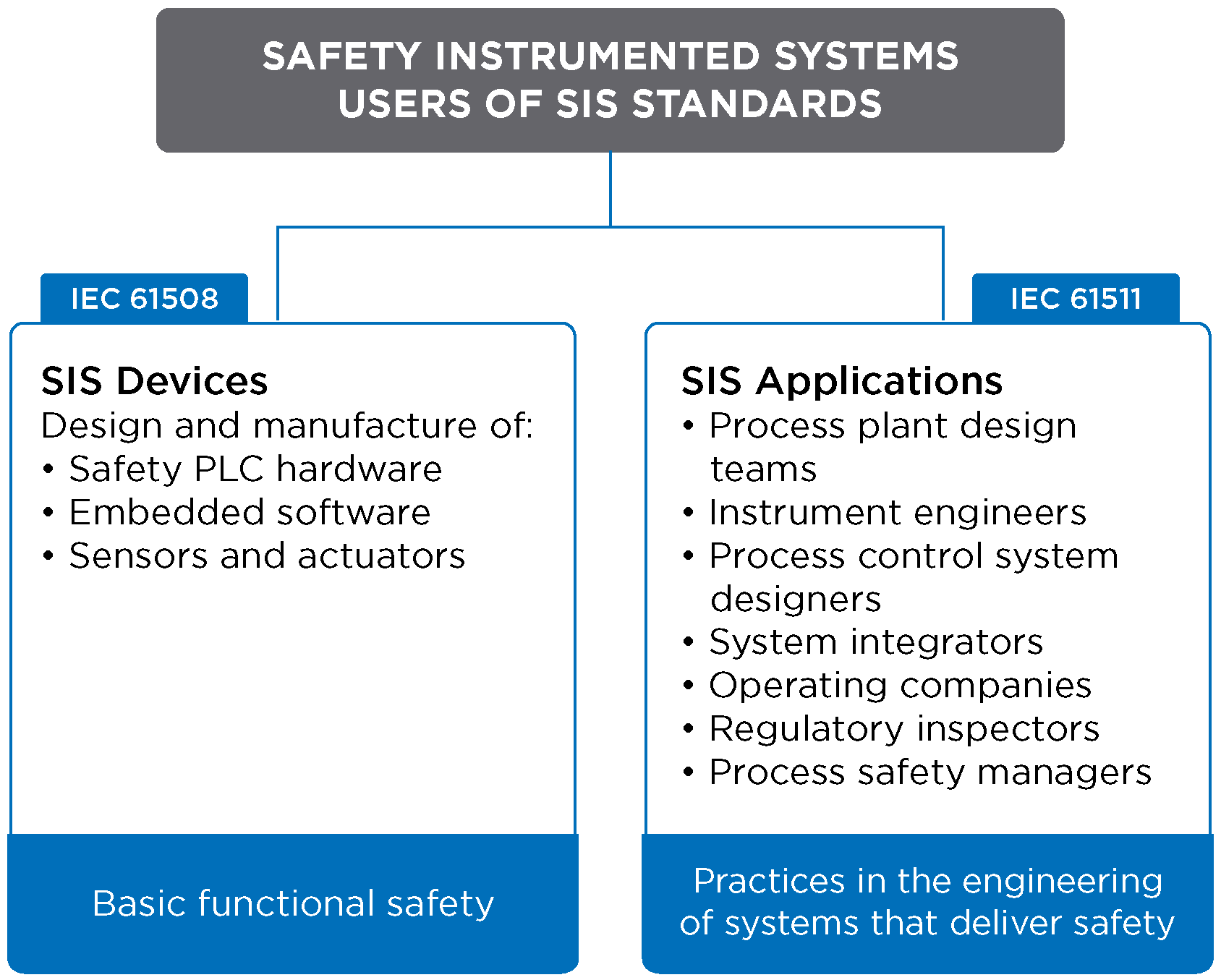
For end users, SIS designers and system integrators, IEC 61511 defines the safety standard they should follow when implementing certified safety equipment. It applies when equipment meets the requirements of IEC 61508, or if Section 11.5 of IEC 615111 is integrated into an overall system used for process sector applications.

Making-the-Most-of-Safety-Integrity-Levels-White-Paper-16085_Graphjics_FIGURE 1- Users of SIS devices and applications

FIGURE 1: Users of SIS devices and applications.

The following aspects must be considered by plant management seeking to comply with international safety standards:

  • What are the potential hazardous events and their associated risks, and what risk reduction is required to achieve tolerable safe process installation?
  • How can it be confirmed that the chosen safeguarding measures and/or equipment achieve the required risk reduction?
  • What activities must be carried out to see that adequate safety is maintained during the entire lifetime of the safeguarded process installation?
  • How can it be established, through proper documentation, that safety requirements are met?

Despite the growing awareness of plant safety issues, not all process manufacturers fully understand the implications of today’s functional safety requirements — or have taken action to achieve compliance at their facilities. This is particularly true for large companies with dispersed global operations, as well as smaller firms with limited engineering resources.

Recognized safety standards such as IEC 61508, IEC 61511 and ANSI/ISA-84.00.01 now represent generally accepted engineering practices for industrial organizations worldwide. In the U.S., for example, the Occupational Safety and Health Administration (OSHA) has endorsed IEC 61511/ISA-84 as a “national consensus standard” for the application of SIS in plant operations. It has stated that employers may be in violation of the General Duty Clause of the Occupational Safety and Health Act of 1970 if plant safety systems do not conform to IEC 61511/ISA-84, and hazards exist related to the SIS, potentially causing serious harm to employees.

CONFORMANCE MEASURES

For new projects, conformance to the IEC 61511 safety standard typically has minimal impact on total project costs. It requires project and operations leaders to follow a structured safety life cycle approach through the design, installation, operation and maintenance of the SIS.

For existing SIS installations, engineering and hardware costs are affected by the regulatory guidelines. Engineering cost will vary based on the quality of the existing process hazards analysis (PHA). If the PHA has established a tolerable risk for the events under review and determined the target risk reduction for the SIF, then less additional engineering is required beyond normal instrumentation and control design. The PFD of the SIF at the current test frequency can be calculated and compared to the required SIL. If the existing PHA has not adequately defined the need for risk reduction (e.g., SIF design or SIL requirements), considerable engineering effort may be required to conform to the standard.

The target SIL for the SIF then will be determined to obtain the risk reduction required to reach tolerable risk for the event. The PFD of the SIF can be calculated to determine if the tolerable risk for the event is achieved. If the SIF cannot meet the target SIL, the test interval might have to be decreased or redundant equipment added. The plant may also have to look at other processes that are inherently safer.

EFFECTIVE COMPLIANCE STRATEGY

Measures for plant safety and regulatory compliance should not be limited to simply installing fail-safe controllers or advanced SIS technology. In fact, to mitigate the risk of serious incidents, it is important to consider safety from all aspects of an operation. Furthermore, plant owners need access to the right resources with the right skills at the right time to restore productivity in the event of safety system failure.

Industrial facilities should take a holistic approach to safety and security, addressing critical requirements from the process control network to the perimeter of the plant. This approach is intended to increase situational awareness of production processes and improve response to emergency situations arising from safety-related incidents. When properly implemented, it will help protect people, assets and the environment while sustaining a high level of operational and business performance.

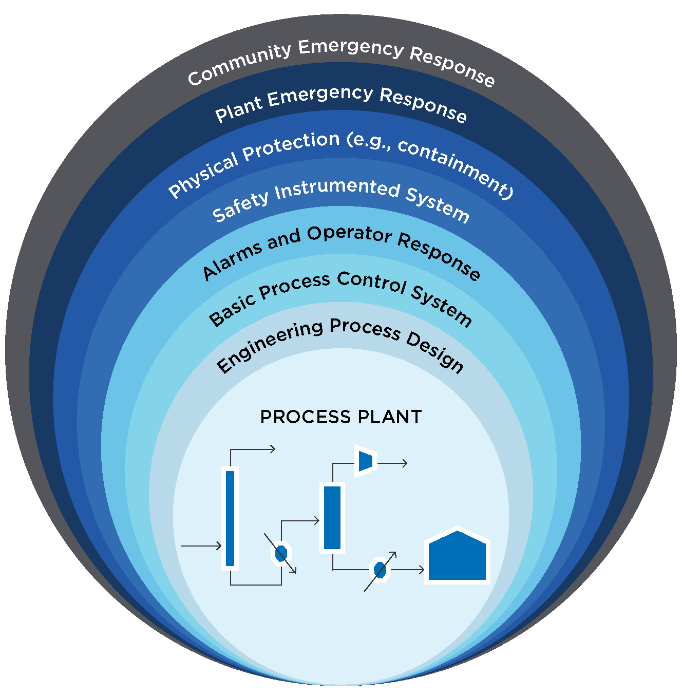
Multiple, independent protection layers (IPL), also known as the “defense-in-depth” approach, generally consists of several independent layers (see Figure 2).

Making-the-Most-of-Safety-Integrity-Levels-White-Paper-16085_Graphjics_FIGURE 2- Typical layers of protection found in process plants

FIGURE 2: Typical layers of protection found in process plants.

Any hardware can fail at one time or another. Failure requires repair or replacement. However, control and safety functions provided within the same hardware show that system failures and repairs leave the process unprotected, which is unacceptable in most operations. There’s also the need to spread risk. Designers and operators of control and safety systems need to prevent one system’s failure from causing devastating effects.

There is no single method that can eliminate all risks. Therefore, several methods must be implemented to reduce the risk of an accident. The concept of protection layers applies to the use of a number of safety measures, all designed to reduce risk by reducing either the likelihood of potential incidents resulting in an impact on people, environment or property or by reducing the magnitude of the impact if an incident occurs.

Each protection layer consists of a grouping of equipment and/or administrative controls that functions in concert with other protective layers to control or mitigate process risk. An independent protection layer should:

  • Be dependable and auditable.
  • Be designed for a specific event.
  • Be independent of other protection layers.
  • Have high availability.
  • Reduce the identified risk by at least a factor of 10.

For an accident to occur, each safety layer would have to fail simultaneously. The more the layers, the lower the probability of all failing simultaneously. The risk can be reduced to very low levels by providing enough protection layers and making each layer highly reliable. However, it must be remembered that the basic process hazards remain and there is always the potential — perhaps very small, but never zero — that all layers might fail simultaneously, and a hazardous incident could occur.

SYSTEM SAFETY LIFE CYCLE

Some plant owners might still wonder whether international safety standards are relevant to their operation. Since there is a growing awareness in process industries of the IEC/ISA standards and because of the association with some regulatory authorities, the answer is yes. However, the operation in question might already have the appropriate safeguards or layers of protection in place, alleviating the need to implement an SIS solution. This can only be determined through the implementation of the safety life cycle, which is a sequential approach to developing a SIS. (References to a safety life cycle can be found in ANSI/ISA‑84.00.01 Parts 1-3 and IEC 61511 Parts 1-3.)

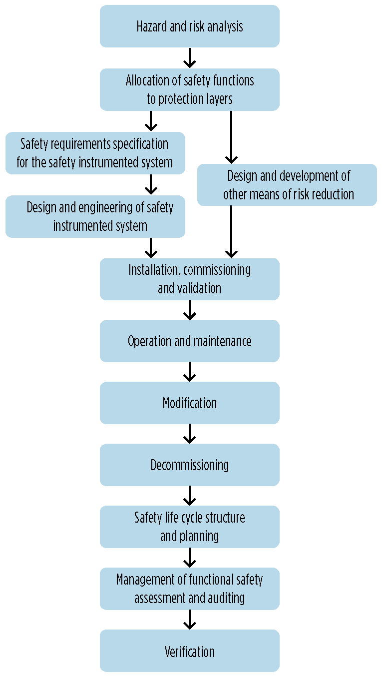
IEC 61511 goes into great detail regarding SIS management. It divides the safety life cycle into a series of key phases encompassing activities from conception through decommissioning. To conform with IEC 61511, each of the requirements outlined in these phases must satisfy the defined criteria. Officially accredited organizations such as Underwriters Laboratories (UL) or TÜV (Technischer Überwachungsverein) can provide independent confirmation that SIS compliance with IEC 61511 has been achieved (see Figure 3).

Making-the-Most-of-Safety-Integrity-Levels-White-Paper-16085_Graphjics_FIGURE 3- IEC 61511 divides the safety life cycle into a series of key phases

FIGURE 3: IEC 61511 divides the safety life cycle into a series of key phases.

Making-the-Most-of-Safety-Integrity-Levels-White-Paper-16085_Graphjics_FIGURE 4- Safety Life Cycle. copy 3

FIGURE 4: Safety Life Cycle.

In general, the implementation of the safety life cycle can follow the IEC/ISA standard in a sequential manner or can be customized to suit the company’s or corporation’s management style.

It is not necessary to develop an extra tier of paperwork to manage this process; integrating the life cycle requirements into existing procedures for planning, designing, constructing and maintaining is perfectly acceptable.

In either case, the safety life cycle is the foundation to build on. This gives the flexibility of implementing some or all the phases based on current requirements. In the first safety life cycle phase, the objective is to analyze the risks involved in running the plant. This involves deciding how much safety risk the operation can tolerate; optionally, the user can also consider other types of harm such as environmental damage, downtime, equipment damage and loss of reputation. In the next period, the SIS is designed to meet the specification. Hardware is selected; calculations are performed to see that the hardware can achieve the specification; software and maintenance procedures are written; and extensive tests and checks are conducted, both before and after the safety equipment is installed. And in the final phase, the plant is operated with the SIS in place. Documentation is prepared on the performance of the system and the demands made on it by the plant. Maintenance of the SIS is carried out as planned, with each change to its design carefully controlled through change management procedures.

CONCLUSION

For process manufacturers, the safety of their plants, facilities, personnel, production operations and the environment has become essential to achieve on-time delivery and minimize any potential losses. The IEC 61511 approach to functional safety has proved to be effective at process industry sites around the world. By utilizing special safety services to help optimize SIS life cycle performance, process safety and availability, plants can reduce interruptions to increase process uptime, maximize effective and efficient utilization of safety assets while improving SIS integrity and availability, and reduce testing and maintenance requirements.

PROJECT STATS

CLIENT
University of Utah

LOCATION
Salt Lake City, Utah

COMPLETION DATE
Spring 2017

CHALLENGE

Established by the U.S. Department of Energy, the Better Buildings Challenge (BBC) program encouraged interested parties to identify savings strategies and reduce energy consumption through facility modifications. The University of Utah signed up for the program and established a revolving savings program internally to fund the project with an overall goal to reduce campus energy use by 20% by 2020.

The university needed a team to identify and quantify energy use along with categorize high energy utilization index (EUI) buildings on their campus. Very quickly, the buildings with high EUIs were identified as the laboratories on campus. Burns & McDonnell could then focus on evaluating energy measures and strategies around the laboratory environment. The BBC’s goal was to not only reduce the energy footprint of campuses, but also to provide economic savings while universities maintained effective facility use. Before any facility modifications could be made to reduce the university’s energy usage, facilities needed to undergo an energy audit to identify inefficient levels of energy consumption occurring around campus.


$1.2M

DESIGN FEES
 

475K

SQUARE FEET RETROFITTED
 

25%

VERIFIED ENERGY SAVINGS

Interested in learning more?

SEND US A NOTE